
I. Introduction
The completed Allen Telescope Array (ATA) is intended to consist of approximately 350 6.1 meter offset Gregorian dishes at the Hat Creek Radio Observatory site in northern California. Given the number of antennas and a very wide field-of-view (2.45° at 21cm wavelength), this array will have an unprecedented amount of flexibility in observing. Several individual users may simultaneously use the array to observe a different part of the sky at an independent frequency, or image the sky at one or more frequencies.
II. Overall Architecture
The ATA has four main conceptual systems:
(1) the antenna collects the radiation from space;
(2) the signal path brings the radiation from the feed (which is located at the antenna focus) back to the user;
(3) the monitor and command systems allow the dishes to be accurately moved, and the signal path controlled. It also monitors the health and status of the array and all of its components;
(4) the site includes the overall antenna configuration, as well as other infrastructure. The ATA will permit remote users to access and use the instrument via a secure Internet connection.
Figure 1 displays the conceptual framework of the ATA and introduces the overall architecture and terminology.
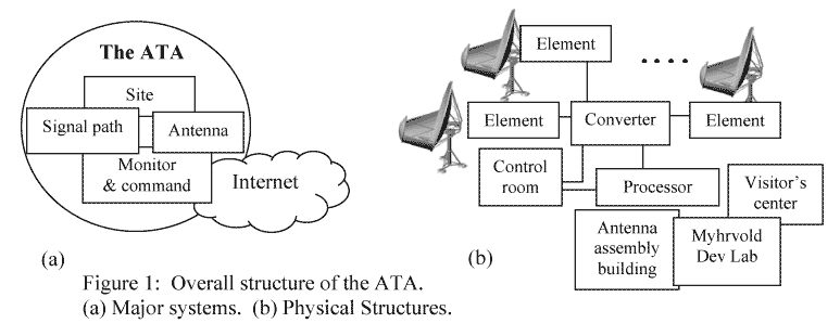
Physically, the ATA consists of many elements (350 when fully built out), which are composed of an antenna and all of the associated mechanical and electrical systems to create the signal path and to monitor and command the array. This build-out number of antennas yields approximately one hectare (10,000 m2) of geometric collecting area. Each element has a pair of analog radio frequency (RF) modulated fiber optic cables for the signal path and additional digital fiber for the monitor and command back to the converter room. The monitor and command fiber is routed directly to the control room, while the analog fiber is processed in the converter and processor rooms before ultimately getting to the user either in the control room or elsewhere via a secure Internet link. In addition, there is an antenna assembly tent for the actual fabrication, and eventually plans for the Myhrvold Development Laboratory, and a visitor's center.
Note that the elements are units highly integrated in the physical structure of the antenna. All of the major components are present at each element. The appearance of the ATA will be dominated by the large number of such elements.
III. Antenna
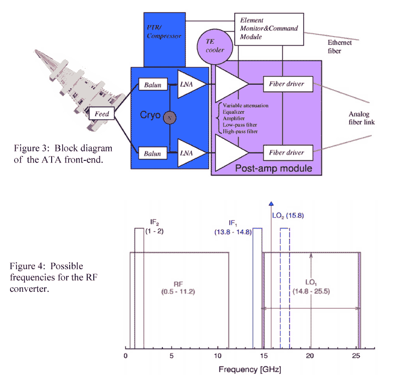
The ATA antenna is a 6.1-meter (approximately 20 foot) offset Gregorian antenna, with a 2.4-meter (8 foot) secondary. These reflecting elements were hydroformed from aluminum in a proprietary process under a contract with Andersen Manufacturing, in Idaho Falls, ID. A metal shroud connects the bottom half of the sub-reflector to the bottom of the primary to deflect ground spillover. The inclusion of the shroud is important in achieving lower system temperatures.
IV. Signal Path
Figure 2 shows the signal path from sky to user. Recall that although just two data paths from one antenna are shown, there would be approximately 700 paths in all antennas for a built-out array. The analog fiber links carry both polarizations of the full 500 MHz - 10 GHz bandwidth back to the RF converter, where it is converted to up to four independent 1 GHz wide dual-polarization channels at L-band. It is then digitized and passed through to the processor.
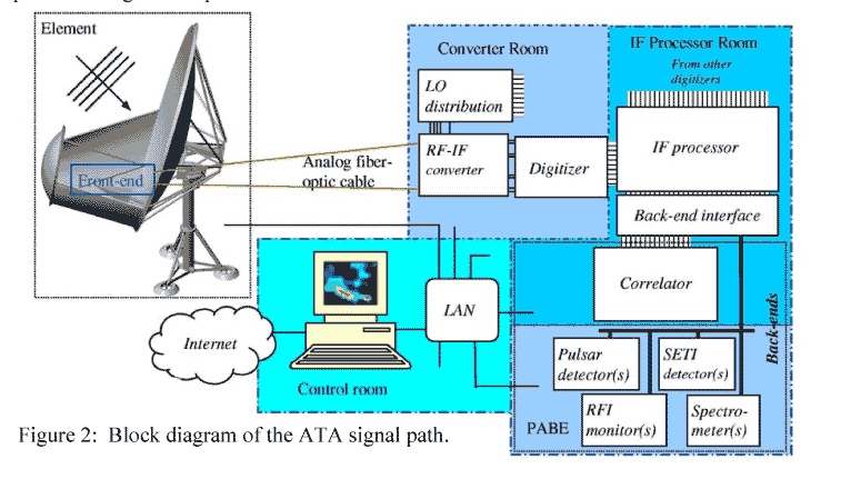
Each of the up-to-four independent tunings is further split into four synthesized beams, which may be steered independently to different parts of the sky. The outputs are sent to either a correlator (which takes all of the signals and makes an image) or one of several phased-array back-ends (PABE’s), or SETI detectors.
V. Monitor and Command
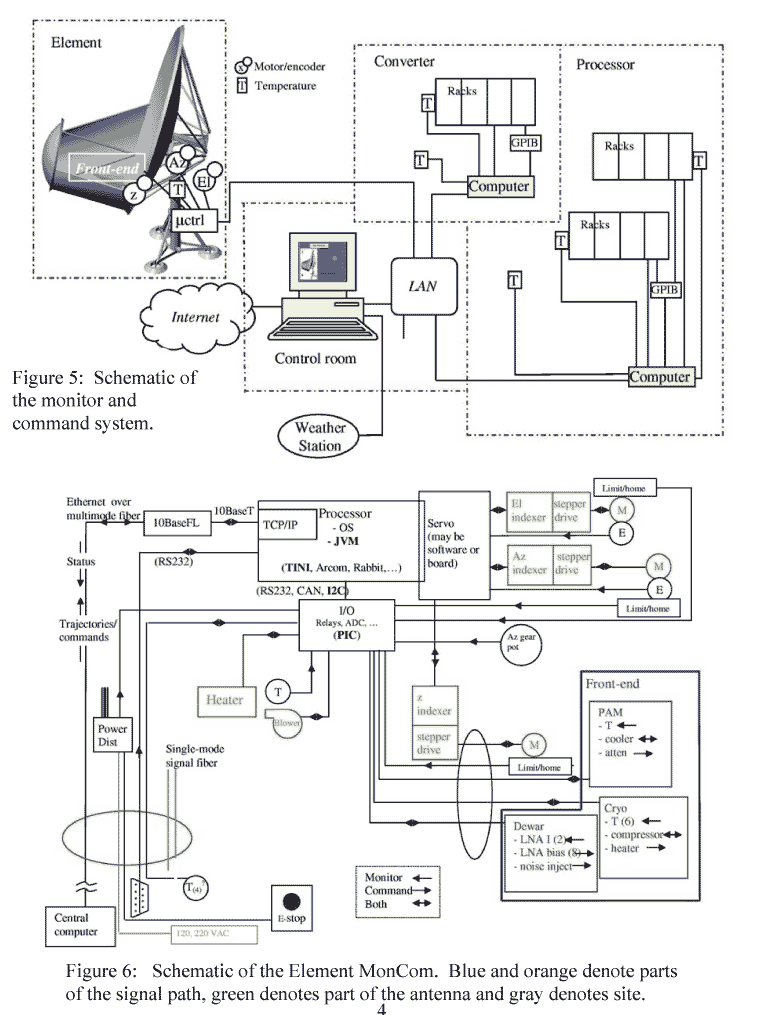
Figure 5 shows a rough schematic of the monitor and command system, a.k.a. MonCom. Recall that although only one element is shown, there are in fact a large number of elements. Standard networking tools are used, making each antenna essentially an “internet appliance.”
VI. Conclusion
The Allen Telescope Array is the first implementation of a large-N, small-D radio telescope. It is a promising candidate for at least a portion of the Square Kilometer Array (SKA).
The ATA is a scalable architecture. It began operation in October 2007 with 42 elements. The rapid increase in computing capability (Moore’s Law) will drive ever-increasing functionality and performance in the digital hardware as the array is built out.